In FPGA development, there's one issue that has always irritated me greatly: the necessity to use huge and sluggish IDEs. Therefore, today we'll dive into an open technology stack for FPGA development.
We'll be working with icestorm — an open-source project initiated by Clifford Wolf in 2015. This is a toolkit for timing analysis, packing, and programming (only through FT2232HL). If we add a synthesis program (yosys) and a place and route tool (nextpnr) to this, we can implement a full development cycle. This means that we can simply install several lightweight programs from apt and start working right away.
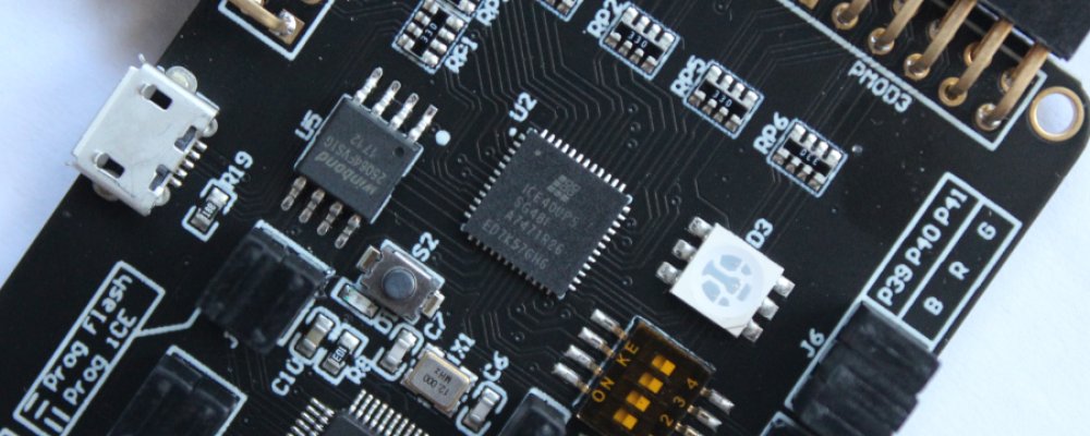
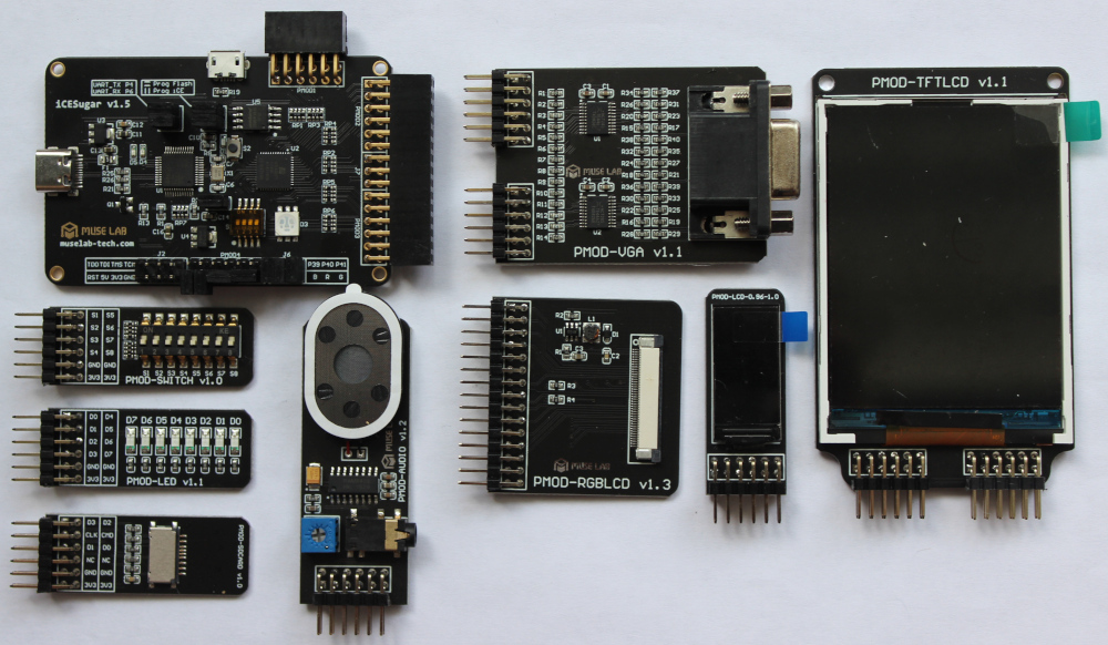
For our work, we will use the iCESugar board, which I purchased here (however, it was out of stock at the beginning of writing this article), together with a bunch of different Pmod modules right away. You can read more about it in the author's blog, hopefully, the fact that it's in Chinese won't stop you. Here, I will reflect on the main interesting points.
In this board, iCELink is used as the programmer, which is essentially a modified DAPLink. Because of this, we cannot program the FPGA using iceprog; it's possible only to drop the compiled binary into the programmer (it creates a block device when connected to a computer), which will lead to its writing to the flash memory chip, from which the FPGA configuration loads at startup. We cannot load the binary directly into the FPGA, bypassing writing to flash, but this programmer has a number of other interesting features. In case we program a soft processor with JTAG support into the FPGA, we can use this programmer as a JTAG debugger for the soft processor. It also creates a virtual COM port and clocks the FPGA at 12Mhz. The schematic of this board can be viewed here.
Setting up the Environment.
First, you need to install the necessary packages:
sudo apt install yosys nextpnr-ice40 iverilog gtkwave fpga-icestormWhere:
- yosys - a framework for synthesizing Verilog RTL.
- nextpnr-ice40 - a place and route tool for ice40 FPGA.
- iverilog - an open-source Verilog simulator.
- gtkwave - a program for drawing timing diagrams from iverilog.
- fpga-icestorm - a set of software for working directly with ice40 FPGA.
This is essentially enough to get started.
A Minimal Example
To ensure the board's functionality, let's run a code for blinking a diode. For this, we need 3 files:
- The program in Verilog language
top.v. - A file describing the physical ports
io.pcf. - A build script
Makefile.
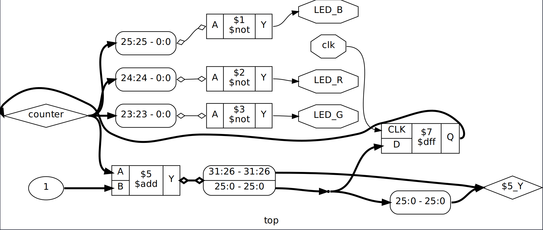
The Verilog code is straightforward, we make a counter on the leading edge of the clock signal and connect an RGB LED to the last 3 bits:
module top(input clk, output LED_R, output LED_G, output LED_B);
   reg [25:0] counter = 0;

   assign LED_B = ~counter[25];
   assign LED_R = ~counter[24];
   assign LED_G = ~counter[23];

   always @(posedge clk)
   begin
      counter <= counter + 1;
   end
endmodule //top
There are no special problems with the description of the ports, just list the used pins and assign them names (immediately along with all the other peripherals on the board):
# For the iCESugar Board (iCE40UP5K-QFN48)

set_io LED_G 41
set_io LED_R 40
set_io LED_B 39

# 12Mhz for iCELink
set_io clk   35

set_io RX    4
set_io TX    6

set_io USB_DP       10
set_io USB_DN       9
set_io USB_PULLUP   11

#spi
set_io SPI_SS   16
set_io SPI_SCK  15
set_io SPI_MOSI 17
set_io SPI_MISO 14
The last thing needed is a script - Makefile:
# Set your parametrs
PROGECT_NAME = template
PCF_FILE = io.pcf
TOP_MODELE = top

# Write your verilog file.
VERILOG_FILES = \
$(TOP_MODELE).v

ICELINK_DEV = /dev/$(shell lsblk -f | grep iCELink |  cut -d ' ' -f 1)
ICELINK_DIR = /tmp/iCELink

build:
    yosys -p "synth_ice40 -top $(TOP_MODELE) -json $(PROGECT_NAME).json" $(VERILOG_FILES)
    nextpnr-ice40 \
        --up5k \
        --package sg48 \
        --json $(PROGECT_NAME).json \
        --pcf $(PCF_FILE) \
        --asc $(PROGECT_NAME).asc
    icepack $(PROGECT_NAME).asc $(PROGECT_NAME).bin

flash:
    mkdir -p $(ICELINK_DIR)
    mount $(ICELINK_DEV) $(ICELINK_DIR)
    cp $(PROGECT_NAME).bin $(ICELINK_DIR)
    sync
    umount $(ICELINK_DIR)

clean:
    rm $(PROGECT_NAME).*
This script expects your top module to be located in a file named like the top module itself, and its name needs to be entered in TOP_MODULE. Also, if desired, you can specify the project name.
The nuances do not end there. Since iCELink is used as the programmer on the board, it's not possible to program the FPGA directly. The FPGA can only be programmed by dragging the firmware file inside the programmer. Therefore, in the makefile, a folder for mounting the programmer is first created (in /tmp/) as a block device. After that, we find the programmer's address in /dev/ through lsblk, then mount it in /tmp/iCELink. This is done specifically so that there are no traces of this folder left after rebooting the system.
If your system is set up for automatic mounting of drives (for example, if you use Ubuntu), then this makefile will not work. This is because the mount command will end with an error, indicating that the volume is already mounted. A Makefile version for an automatically mounted device can be viewed here.
To compile and load the code, you need to execute the following commands:
make
sudo make flash
Next, I suggest we take a closer look at the software we use for work.
Yosys
Yosys written in C++, allows converting Verilog files into BLIF (Berkeley Logic Interchange Format) / EDIF (Electronic Design Interchange Format) and other formats. Essentially, it synthesizes connections for FPGA. This package allows working with Xilinx 7-Series and Lattice iCE40 FPGAs.
In the makefile, a command equivalent to this was used:
yosys -p "synth_ice40 -top top -json led.json" led.vEssentially here are 2 parameters - the name of the Verilog file we read for analysis and the script we pass in double quotes after the -p key. In this script, we launch the synth_ice40 macro needed for synthesis under ice40. Other macros for other FPGAs can be viewed here. This macro needs to be passed parameters - the name of the top module -top top, and the name of the json file where to write the synthesis result -json led.json.
There's an alternative way to use this software - manually, not through a makefile.
yosysThen a console appears before us, working with the program consists of sequentially calling different stage commands working with the Verilog file. The main commands:
- read_verilog - reads Verilog file;
- hierarchy - constructs the hierarchy of the Verilog file or project;
- proc - processes always blocks;
- opt - conducts optimization if possible;
- techmap - allows mapping each circuit element;
- show - display the device scheme in graphical form. A dot file is created and displayed using Graphviz.
yosys> read_verilog led.v
yosys> hierarchy
yosys> proc
yosys> opt
yosys> show
yosys> techmap
yosys> show
The first show will output an RTL-level scheme, the second will show connections at the lut level. The schemes are not very readable, possibly this can be corrected, but I did not delve into this.
nextpnr-ice40
To manually run this software package, execute the following command:
nextpnr-ice40 --up5k --package sg48 --json led.json --pcf io.pcf --asc led.ascThis program can also be run in graphical mode, but for this, you need to install the following package through apt: nextpnr-ice40-qt.
nextpnr-ice40 --up5k --package sg48 --json led.json --pcf io.pcf --asc led.asc --guiTo display connections, you need to go through the chain of commands: Pack->Place->Route.
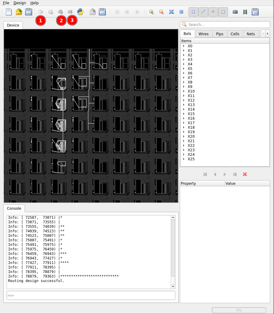
Icestorm
icestorm includes the following packages:
- IcePack/IceUnpack - firmware packing/unpacking program into a binary file, all icestorm utilities use ASCII format.
- Icetime - a simple timing analysis program, or assembly of files for external timing analysis programs.
- IceProg - Program for programming chips through FTDI programmers.
- IceMulti - Packer of several binary files into one image.
- IcePLL - a program for calculating iCE40 PLL configuration parameters.
- IceBRAM - a program for loading FPGA BRAM content into an ASCII file.
We only need one program from all of this - icepack:
icepack led.asc led.binsince for programming, we simply drag and drop the file into the programmer's folder.
Icestudio
I also found a very interesting IDE for graphical FPGA programming - Icestudio, which supports the board we are considering. This little program is written on top of Chrome (electron), and operates on Python, creating a virtual execution environment in the folder ~/.icestudio, and after work, this folder weighs about a gigabyte. As a serious development tool, I would not consider this program, but to assemble a bit of schematics in graphical mode is quite possible.
To install, you need to install the following dependencies:
sudo apt install python3 python3-pip python3-venv xclipAfter that, download the archive with the appimage from here, unpack it, give execution rights, and run:
chmod +x icestudio-0.9.1w202204070704-linux64.AppImage
./icestudio-0.9.1w202204070704-linux64.AppImage
Next, you need to install the necessary tool sets, this will be offered to do in the GUI, it is described in detail here. After that, you will be offered to install drivers, agree to that too. Everything is clickable.
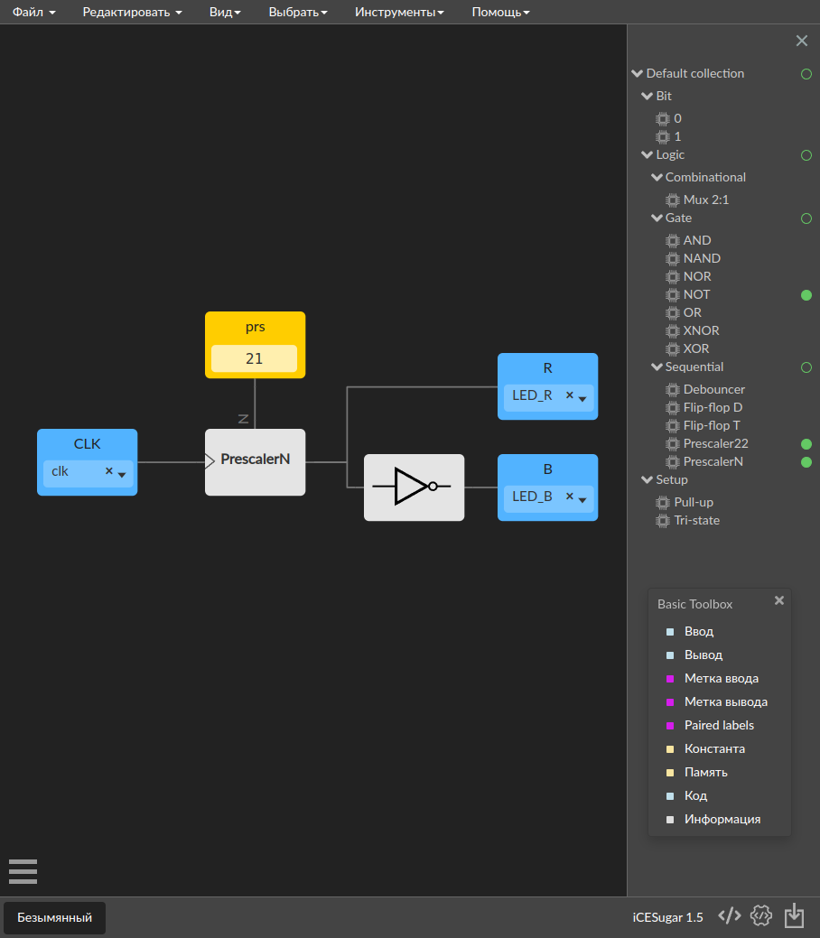
To open the Basic Toolbox, you need to press Ctrl + T or Edit->Toolbox. This menu is necessary for selecting inputs and outputs on the board. Basic components are located in the Default collection on the right. If they are not enough, you can install other collections.
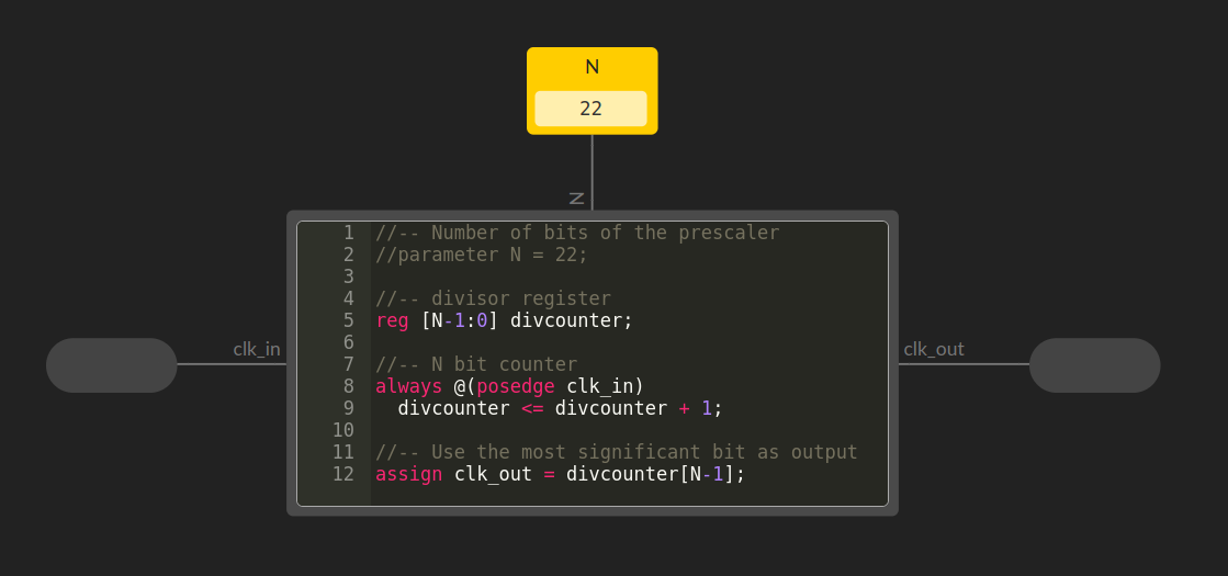
По своей сути каждый блок это просто кусок кода написанного на verilog, например блок делителя частоты:
There is a possibility to create your own blocks, which is described here, though it's not clear why one would bother.
Interesting Links
- iCESugar project with schematics and examples.
- Blog of the creator of iCESugar.
- Website of the Yosys project and its git.
- nextpnr project.
- icestorm website.
- Icestudio and documentation for it.