The method of working with the official plugin described in the previous article turned out to be not the most convenient in practice. Therefore, today we will go over how to manually configure VS Code to work with STM32 controllers. We will also cover the basic principles of setting up VS Code, which can be useful for other similar projects.
To start, let’s explore why I believe the manufacturer's plugin is not suitable for development. Here are the main issues I see:
- Dependency on IntelliSense, which means it cannot be used with VSCodium or Code - OSS (at least if you adhere to the Terms of Use).
- The use of CMake Tools, which creates a redundant window and, on top of that, automatically runs
cmakeevery time you open a project. This extension adds no value and only gets in the way. - The plugin creates an unnecessary window by itself, cluttering
VS Codewith unwanted features. - It requires the use of STM32CubeCLT, which adds unnecessary tools to the system, especially when a compiler and utilities from repositories are already being used. Most importantly, it removes flexibility: you are forced to use the ST-LINK server instead of alternatives like OpenOCD or PyOCD (even though these are supported by Cortex Debug).
These factors collectively lead us to the decision to completely abandon the STM32 VS Code Extension.
Next, we should ask ourselves: what do we want from a code editor in the 21st century? I would highlight three main aspects:
- Build
- Debugging
- Static Analysis
Let’s explore how VS Code is designed to handle each of these tasks. However, before diving in, we need to create a project. You can follow the instructions from the previous article (Project Creation -> Cube MX), or you can use any other configuration and controller. The key requirement is that the project must be generated specifically for CMake.
Project Creation
Next, create a folder named App with test code, exactly as described in the section Organizing a C Project. To ensure everything is working correctly, you can build the code using the terminal. This is quite simple to do while in the project folder:
mkdir build && cd build
cmake ..
cmake --build .
For this to work, the arm-none-eabi-gcc toolchain must be installed on your system. You can install it using your package manager:
sudo pacman -S arm-none-eabi-gcc arm-none-eabi-newlib # Arch linux
sudo apt install arm-none-eabi-gcc # Debian based
Alternatively, you can download the binaries directly from the ARM website.
Build
VS Code provides a mechanism called tasks to handle tasks like building or running commands. Essentially, a task is just a wrapper around a console command that can be executed from the terminal or through other methods.
In our case, another way to trigger tasks is by adding buttons to the status bar. To enable this, you need to install the Tasks extension.
The configuration for statuses and commands is done in the .vscode/tasks.json file. Here's an example configuration:
{
    "version": "2.0.0",
    "tasks": [
        {
            "label": "clean",
            "group": "build",
            "type": "shell",
            "command": "rm -rf build",
            "options": {
                "statusbar": {
                    "color": "#ff8b8b",
                    "label": "$(clear-all) Clean",
                    "detail": "Clean ALL"
                }
            }
        },
        {
            "label": "Configure_Debug",
            "group": "build",
            "type": "shell",
            "command": "cmake -S . -B build -DCMAKE_BUILD_TYPE=Debug",
            "options": {
                "cwd": "${workspaceFolder}",
                "statusbar": {
                    "color": "#8bdeff",
                    "label": "$(gear) Debug",
                    "detail": "Cmake configure Debug"
                }
            }
        },
        {
            "label": "Configure_RelWithDebInfo",
            "group": "build",
            "type": "shell",
            "command": "cmake -S . -B build -DCMAKE_BUILD_TYPE=RelWithDebInfo",
            "options": {
                "cwd": "${workspaceFolder}",
                "statusbar": {
                    "color": "#8bdeff",
                    "label": "$(gear) RelWithDebInfo",
                    "detail": "Cmake configure RelWithDebInfo"
                }
            }
        },
        {
            "label": "Configure_Release",
            "group": "build",
            "type": "shell",
            "command": "cmake -S . -B build -DCMAKE_BUILD_TYPE=Release",
            "options": {
                "cwd": "${workspaceFolder}",
                "statusbar": {
                    "color": "#8bdeff",
                    "label": "$(gear) Release",
                    "detail": "Cmake configure Release"
                }
            }
        },
        {
            "label": "Configure_MinSizeRel",
            "group": "build",
            "type": "shell",
            "command": "cmake -S . -B build -DCMAKE_BUILD_TYPE=MinSizeRel",
            "options": {
                "cwd": "${workspaceFolder}",
                "statusbar": {
                    "color": "#8bdeff",
                    "label": "$(gear) MinSizeRel",
                    "detail": "Cmake configure MinSizeRel"
                }
            }
        },
        {
            "label": "build",
            "group": "build",
            "type": "shell",
            "command": "cmake --build build",
            "options": {
                "cwd": "${workspaceFolder}",
                "statusbar": {
                    "color": "#8bff97",
                    "label": "$(code) Build",
                    "detail": "Build"
                }
            }
        }
    ]
}
This configuration creates buttons (and customizes them) for each type of configuration described in CMakePresets.json, as well as adding clean and build commands. I believe the configuration is already clear enough, and additional explanations are unnecessary.
In fact, the tasks mechanism in VS Code is quite complex and interesting. For example, you can create dependent tasks. If your application requires a server to run, you can set up the server to start before the application, make it dependent, and specify a regular expression to analyze its logs. This allows the process to stop in case of errors. However, all of this is a topic for another time — such functionality is not required for working with STM32.
Debugging
VS Code allows you to connect to a GDB server via plugins and, by parsing its output, enables debugging directly within the editor. For working with C/C++ on microcontrollers, three solutions are available:
- Cortex-Debug - This is the most popular plugin for working with ARM architecture. We will focus on this one. You can find more details about working with this plugin in the previous article, and here we will only discuss its configuration.
- The official Microsoft plugin — C/C++ for Visual Studio Code - This plugin can be used with microcontrollers, but it requires a bit more effort to configure. However, we will avoid using it for the reasons already mentioned above.
- Native Debug - An interesting plugin that works with both
GDBandLLDB. It can also be configured to work with Cortex microcontrollers, but it is somewhat more complex thanCortex-Debugdue to its broader versatility. We will stick with the first option, though this plugin might be useful in future articles if we cover RISC-V programming.
To work with Cortex-Debug, your computer must have GDB installed (using gdb-multiarch rather than arm-none-eabi-gdb), as well as OpenOCD:
sudo pacman -S openocd gdb # ARCH Linux
sudo apt install openocd gdb # Debian based
As mentioned earlier, it is possible to use PyOCD or the J-Link server. However, these tools will not be covered in this article, as OpenOCD handles almost all tasks in the context of working with STM32.
Before configuring VS Code, it is better to first verify the functionality of OpenOCD and GDB in the terminal. To do this:
openocd -f interface/stlink.cfg -f target/stm32g4x.cfg
# Another Terminal
telnet localhost 4444
> reset halt
> flash write_image erase /home/zen/projects/stm32/vscode-cubemx-pro-guide/build/vscode-cubemx-pro-guide.hex
> reset
To build HEX files in addition to ELF, you need to add the following lines to the end of CMakeLists.txt (as described in the previous article):
...
# Add custom commands to generate .bin and .hex files
add_custom_command(TARGET ${CMAKE_PROJECT_NAME} POST_BUILD
COMMAND ${CMAKE_OBJCOPY} -O binary $<TARGET_FILE:${CMAKE_PROJECT_NAME}> ${CMAKE_PROJECT_NAME}.bin
COMMAND ${CMAKE_OBJCOPY} -O ihex $<TARGET_FILE:${CMAKE_PROJECT_NAME}> ${CMAKE_PROJECT_NAME}.hex
COMMENT "Building ${CMAKE_PROJECT_NAME}.bin and ${CMAKE_PROJECT_NAME}.hex"
)
Additionally, on Arch Linux, the inetutils package must be installed for telnet to work.
After this, the board should be flashed, and the LED on it should start blinking.
Next, you can verify the functionality of the GDB server. To do this, start the server:
gdb
> target remote localhost:3333
> monitor reset halt
> monitor flash write_image erase /home/zen/projects/stm32/vscode-cubemx-pro-guide/build/vscode-cubemx-pro-guide.hex
> c
To work with GDB, OpenOCD must be running. The topic of debugging using the console version of GDB will (likely) be covered in future articles.
In VS Code, the Cortex-Debug extension automates all these actions without requiring manual intervention. To enable this, you simply need to configure the .vscode/launch.json file:
{
    "version": "0.2.0",
    "configurations": [
        {
            "name": "STM32",
            "cwd": "${workspaceRoot}",
            "executable": "build/${workspaceFolderBasename}.elf",
            "request": "launch",
            "type": "cortex-debug",
            "servertype": "openocd",
            "preLaunchTask": "build",
            "gdbPath": "gdb",
            // Add you svd file
            // "svdFile": "${workspaceRoot}/Docs/STM32F3x4.svd",
            // Set you programmer and trget controller
            "configFiles": [
                "interface/stlink.cfg",
                "target/stm32g4x.cfg"
            ],
            // "runToEntryPoint": "main",
            "showDevDebugOutput": "none",
            "swoConfig": {
                "enabled": true,
                "swoFrequency": 2000000,
                "cpuFrequency": 170000000,
                "decoders": [
                    {
                        "port": 0,
                        "type": "console"
                    }
                ]
            }
        }
    ]
}
Important points about this configuration:
servertype— You can use not onlyopenocdbut also other values, such aspyocdorjlink.preLaunchTask— This is the task we configured in the previous section.gdbPath— Path toGDB. If you are using the systemgdb-multiarch, simply specifyinggdbis sufficient.svdFile— Path to the file describing the register addresses, which can be helpful for debugging as it makes them viewable in the debugger. Such a file can be downloaded from the ST website. For example, for the STM32G431, it is available here (you need the STM32G4 System View Description file).configFiles— Configuration files that define the debugger and the controller series. These parameters are passed toOpenOCD.runToEntryPoint— Stops execution at the start of themainfunction.swoConfig— Activates the SWO console. For it to work, you must specify the correct processor frequency in thecpuFrequencyparameter. To useprintf()with SWO, you need to override the_write()function:
// For use SWO
int _write(int file, char *ptr, int len) {
  (void)file; // hack for fix warning - unused int file.
  for (int i = 0; i < len; i++)
    ITM_SendChar((*ptr++));
  return len;
}
For more details about SWO configuration, see here.
Static Analysis
In this section, I will discuss tools that assist in writing code, such as snippets, linters, autocompletion, autoformatting, syntax highlighting, etc. When using the ST extension, these features are typically handled by C/C++ for Visual Studio Code. However, as mentioned multiple times in this article, we will avoid using it.
This functionality will instead be built around the clangd language server and the clangd plugin. For this system to work, clangd must be installed on your system:
sudo pacman -S clangd # ARCH Linux
sudo apt install clangd # Debian based
This language server uses the list of source files from compile_commands.json to construct the syntax tree. By default, CubeMX adds a line to CMakeLists.txt that enables the generation of the compile_commands.json file.
However, since clangd is initially designed to work with the clang toolchain, additional configuration is required to use it with gcc. Further setup is done in the .vscode/settings.json file:
{
    "clangd.arguments": [
        "--compile-commands-dir=build",
        "--enable-config",
        "--clang-tidy",
        "-j=12",
        "--completion-style=detailed",
        "--suggest-missing-includes",
        "--header-insertion-decorators",
        "--background-index",
    ]
}
However, due to the specifics of command-line argument parsing, it is necessary to use the --enable-config parameter and create a separate .clangd file in the project root with additional build options:
CompileFlags:
  Add:
    - "-I/usr/arm-none-eabi/include"
    - "-D__INT32_TYPE__=long"
    - "-D__UINT32_TYPE__=unsigned long"
In the .clangd file, you need to specify includes from newlib and override the long type. This is necessary because its size differs between 32-bit and 64-bit systems.
Among other parameters, you should adjust the value of -j=12 to match the number of cores on your processor. The rest can remain unchanged. A description of the available parameters can be obtained using the following command:
clangd --helpAfter creating the configuration files, restart VS Code. In the PROBLEMS tab, you will see all the issues identified by the static analyzer.
This is not the only static analyzer that can be used. In fact, there are quite a few, but most of them are paid. There is a plugin for VS Code that allows you to combine several analyzers — C/C++ Advanced Lint.
Among the tools supported by this plugin, we are particularly interested in CppCheck due to its extensive capabilities in the free and open version. We will not use the other analyzers (but feel free to try them out on your own if desired).
The configuration of this plugin is also done through the .vscode/settings.json file:
...
    // Advanced Lint
    "c-cpp-flylint.clang.enable": false,
    "c-cpp-flylint.flexelint.enable": false,
    "c-cpp-flylint.cppcheck.enable": true,
    "c-cpp-flylint.lizard.enable": false,
    "c-cpp-flylint.flawfinder.enable": false,
    "c-cpp-flylint.cppcheck.standard": [
        "c11",
        "c++20"
    ],
    "c-cpp-flylint.cppcheck.severityLevels": {
        "error": "Error",
        "warning": "Warning",
        "style": "Information",
        "performance": "Information",
        "portability": "Information",
        "information": "Information"
    },
    "c-cpp-flylint.cppcheck.suppressions": [
        "cstyleCast"
    ],
    "c-cpp-flylint.cppcheck.extraArgs": [
        "--cppcheck-build-dir=build",
        "--platform=arm32-wchar_t2",
        // "--addon=misra.py",
        "--enable=all",
        "--force",
        "-j12",
        "-D__GNUC__",
        "-D__INT32_TYPE__=long",
        "-D__UINT32_TYPE__=\"unsigned long\"",
        "-I/usr/arm-none-eabi/include",
    ]
...
The clangd analyzer is disabled in this configuration since it is already running as part of the previous plugin.
To use this setup, cppcheck must be installed on your system:
sudo pacman -S cppcheck     # ARCH Linux
sudo apt install cppcheck   # Debian based
Cppcheck is a fairly advanced static analyzer with many options. You can read more about its usage here. It even includes partial support for MISRA C in its free version. However, since HAL does not adhere to MISRA, this option is not enabled in my configuration.
Additional Plugins for Enhanced Workflow
For a more convenient and efficient workflow, consider installing the following plugins:
- Error Lens - Displays errors and warnings directly on the code line, similar to Qt Creator.
- Better C++ Syntax - Enhances syntax highlighting for C/C++.
- C/C++ Snippets - Provides useful snippets for C/C++.
- Plugins for working with CMake:
- CMake — Adds basic syntax support.
- cmake-format — Adds autoformatting. For this plugin to work, cmake-format must be installed on your system.
- Plugins for documentation:
- Doxygen — Adds support for
Doxygensyntax. - Doxygen Documentation Generator — Automatically generates function descriptions based on their declarations.
- Doxygen — Adds support for
- Highlighting for specific formats:
- GNU Linker Map files — Highlights the syntax of
mapfiles. - LinkerScript — Adds syntax highlighting for linker scripts.
- GNU Linker Map files — Highlights the syntax of
Regularly check for new plugins that might improve your workflow with the file types you use. Someone may have already created a plugin to solve your problem, simplifying your work.
As a result, the setup will look like this:
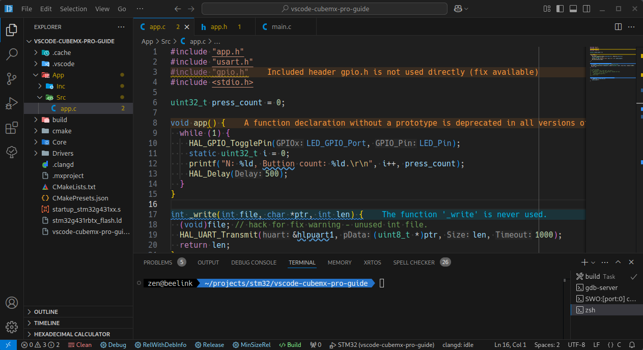
Installed Plugins
- Tasks - Adds task buttons to the status bar.
- Cortex-Debug - Plugin for debugging.
- Сlangd - Plugin for the
clangdlanguage server. - C/C++ Advanced Lint - Supports multiple syntax analyzers.
- Error Lens - Displays errors directly in the code.
- Better C++ Syntax - Improves syntax highlighting.
- C/C++ Snippets - Provides a collection of snippets.
- CMake - Basic support for
CMake. - Cmake-format - Autoformats
CMakescripts. - Doxygen - Adds support for
Doxygensyntax. - Doxygen Documentation Generator - Generates function descriptions based on declarations.
- GNU Linker Map files - Highlights linker files.
- LinkerScript - Highlights linker scripts.
You can also automatically add these plugins to your system by creating an extensions.json file in the .vscode folder:
{
  "recommendations": [
    "actboy168.tasks",
    "marus25.cortex-debug",
    "llvm-vs-code-extensions.vscode-clangd",
    "jbenden.c-cpp-flylint",
    "usernamehw.errorlens",
    "jeff-hykin.better-cpp-syntax",
    "hars.CppSnippets",
    "twxs.cmake",
    "cheshirekow.cmake-format",
    "bbenoist.Doxygen",
    "cschlosser.doxdocgen",
    "trond-snekvik.gnu-mapfiles",
    "ZixuanWang.linkerscript"
  ]
}
Links
- Project on GitHub with an example from the article.
- Documentation for VSCode.